
Propeller Aircraft

Hey, what is up folks hope you all are doing well. In the last blog, we discussed all the various topics for your DGCA exams and how to get your computer number. Now before we start with any of the concepts in details, I want to talk a bit about the essential components of a propeller-driven aircraft and the functions they serve, build the basics.


Starting from the propeller, we are gonna go clockwise and talk about each and every component marked in this diagram of a propeller-driven A/c. So, dig in!

  1. The propeller: Well in a propeller-driven aircraft it is this part which pulls in the air in front of the aircraft (A/c) providing it with a forward thrust.

  2. The engine: I don't suppose I need to explain much, but here's something to get your basics right! The engine is the component that makes the propeller turn and enables the A/c to function. The metallic cover that covers the engine is known as the COWLING.

  3. The fuel tank: Its definition is quite literal; it stores fuel.

  4. The radio antenna: It is the device used for transmitting and receiving radio signals which in turn is used for communication.

  5. Vertical and Horizontal stabilizer: Well first of all the stabilizer's job is to provide stability to the A/c and to make sure it flies straight. The vertical stabilizer prevents the nose of the A/c from moving side to side; this move is also known as YAWING. The horizontal stabilizer prevents the up and down motion of the nose; this movement is known as PITCHING.

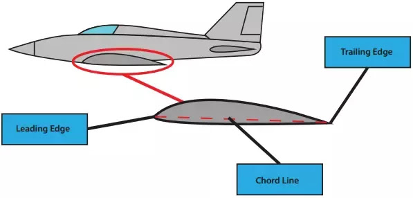
  6. Navigation lights: These lights are located on the tips of the leading edge of the wings. Each wing has two edges, one to the front is known as the Leading-edge, and the one to the rear is known as the Trailing-edge. The leading edge of the right wingtip houses a RED navigational light whereas the leading edge of the left wingtip houses a GREEN navigational light.                                                                                                                                                                                                        
  7. The flashing beacon: You see it at the tip of the vertical stabilizer. The flashing beacon is a blinking WHITE navigational light. It is these 3 white, red and green lights placed at 3 different extremities of the A/c that gives us info about the position both on the ground and in air, heading, i.e. the direction of the A/c and the status of the A/c.

  8. The landing gear: Also known as the UNDERCARRIAGE of the A/c; the landing gear houses the main and the nose wheel, which are used to take off and land. 
  9. The Fuselage: The main body of the A/c is the Fuselage. It is this part that holds the passengers, the crew, the cargo and in single-engine A/c's like the one in the reference picture it also contains the engine.
Now you may be wondering that I missed out a few parts like the Aileron or the Rudder and a few more. Well, these parts fall under a different category known as the CONTROL SURFACES of the A/c which serve a vital role of helping the pilot manoeuvre the A/c and need some special love and attention all to themselves. So, we will be discussing in-depth about these control surfaces in the next blog. Until then keep dreaming big, and this is your Soaring Pilot signing off ðŸ›«ðŸ’–.


For all the latest updates follow me on:

Comments

Popular posts from this blog

Bernoulli's Principle

Hey, what is up folks hope you all are having a wonderful day. On today's blog, we will discuss a very basic topic that most of us have already learned back in school, BERNOULLI'S PRINCIPLE .  So, without any further ado, let's get straight into it, shall we?  Alright, so in fluid dynamics, Bernoulli's Principle states that an increase in the speed of a fluid co-occurs with a decrease in static pressure or a decrease in the fluid's potential energy and vice-versa. A quick note air-flow is treated as a fluid. Now, let's understand what all the fuss about. To do so we're gonna take the help of a VENTURI TUBE . Alright, folks so this what a venturi tube looks like. So let's start from the extreme left of the tube, we can see it has a large area of cross-section facilitating the flow of the fluid with HIGH PRESSURE and LOW SPEED . As we move towards the right we can see the tube converging into an area with a much smaller cross-section, and it is due to thi

Control Surfaces of Aircraft

Hey, what is up folks hope you all are doing well. In the last blog, we discussed the different parts and the functions they serve in a propeller-driven A/c. This article is a follow up to that blog. Today, we will be talking about the CONTROL SURFACES of an A/c. Now before we start our discussion about the control surfaces, we first need to talk about the 3 different axes about which an A/c can move. The first one being the LATERAL  axis, marked in yellow. It spans from wingtip to wingtip. The second one is the LONGITUDINAL  axis, marked in blue. It spans from the nose to the tail of the A/c. The third one is the VERTICAL or NORMAL axis, marked in red.                                                                                                      Note that all 3 of these axes pass through the CENTRE OF GRAVITY (CG) of the A/c. Alright, now that we know of the 3 different axes about which an A/c can manoeuvre, we need to talk about the parts that enable the A/c to do so.  Those b